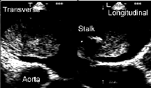
 Biplane image of a left atrial myxoma.
Using commercially available Computer Aided Design programs, it is possible to view the relationships between simultaneous longitudinal and transverse echocardiograms. The following script file creates a three dimensional grid on to which two dimensional echocardiograms can be placed in apposition to one another at a ninety degree angle. Annotations with corresponding graphical depictions appear bold in the course of the script.
 Biplane image of a left atrial myxoma.
Part A: Setting up the Grid System
The following steps illustrate how the template grid is created. All graphics are scaled to 50% of their actual size
1. setting up the environment and creating the grid's primary frame:
new
echo1
pline 8.7,4.3,0 5,8 1.3,4.3
At this point, the grid appears as follows:

2. Adding the grid lines to demarcate the 0.2 cm grid radiations
Arc C 5,8 5,2.8 A 45
Arc C 5,8 5,2.8 A -45
Arc C 5,8 5,3.2 A 45
Arc C 5,8 5,3.2 A -45
Arc C 5,8 5,3.6 A 45
Arc C 5,8 5,3.6 A -45
Arc C 5,8 5,4.0 A 45
Here is a partially completed grid: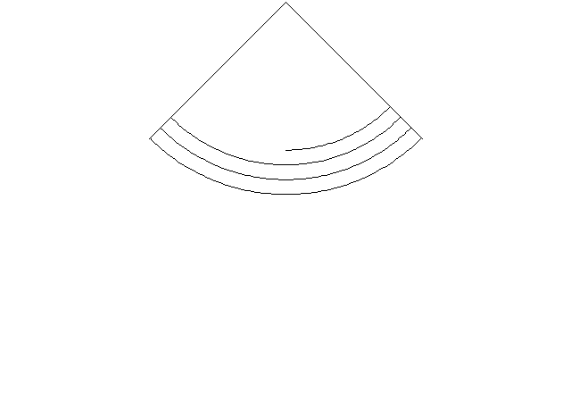
Arc C 5,8 5,4.0 A -45
Arc C 5,8 5,4.4 A 45
Arc C 5,8 5,4.4 A -45
Arc C 5,8 5,4.8 A 45
Arc C 5,8 5,4.8 A -45
Arc C 5,8 5,5.2 A 45
Arc C 5,8 5,5.2 A -45
Arc C 5,8 5,5.6 A 45
Arc C 5,8 5,5.6 A -45
Arc C 5,8 5,6.0 A 45
Arc C 5,8 5,6.0 A -45
Arc C 5,8 5,6.4 A 45
Arc C 5,8 5,6.4 A -45
Arc C 5,8 5,6.8 A 45
Arc C 5,8 5,6.8 A -45
Arc C 5,8 5,7.2 A 45
Arc C 5,8 5,7.2 A -45
Arc C 5,8 5,7.6 A 45
Arc C 5,8 5,7.6 A -45
Here is the grid at completion: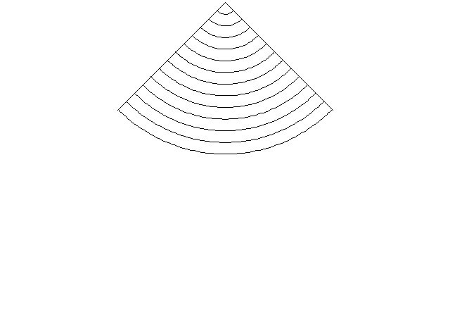
3. The appropriate scale for this grid is applied (scale = 0..5984848) to calibrate it with the real environment
scale window 1.142,2.7 8.8,8.2
5,8,0 0.5984848
After scaling: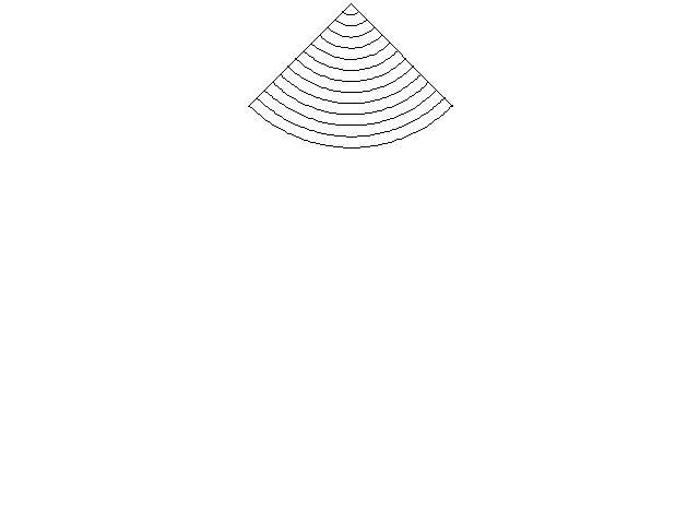
4. The second grid is copied from the first
copy window 2.6,4.8 7.4,8.1
5,8,0 10,8,0
Here are the two grids: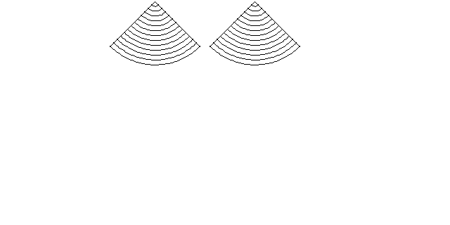
5. The second grid is rotated 90 degrees in 3D space:
rotate3d window 7.67,4.77 12.32,8.14
y 10,8,0 90
Here are the two grids after the maneuver: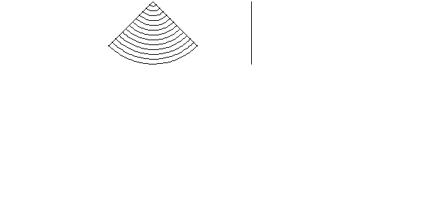
6. The second grid is moved in position perpendicular to the first:
move window 7.67,4.77 12.32,8.14
10,8,0 5,8,0
Here is the completed grid: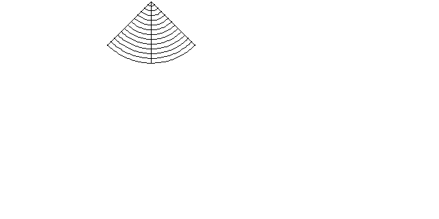
8. At this point, the grid is saved in this position so as to provide a template:
dxfout c:\data\acad\grid.dxf 16
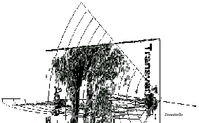
9. From this point, the grid can be manipulated in three dimensional
space, as exemplified here: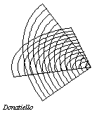
dview window 2.6,4.8 7.4,8.1
ca -30.65 -30.65 x
Part B: Method #1 for Importing Biplane Views
The following is another script file that continues from the point after the grid template was created. This routine imports two GIF images and places them in the appropriate positions on the grids.
1. Preparation of the images: Using a graphics manipulation program, the single biplane image is essentially divided in two. However, the side removed is filled in with the background color, so as to avoid disrupting the scale of the original when it is imported into the grid system.

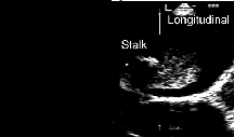
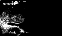
2. Load the grid system (for the purposes of this example, the files are located in a directory labeled 'c:\data\grid'):
dxfin c:\data\grid\echo4.dxf
3. Import the first graphic (longitudinal view) and scale it to the appropriate size (scale factor = 2.965517241):
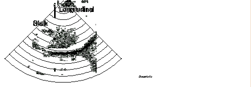
gifin c:\data\grid\mx4grd2l.gif
3.5132,5.0326,0 2.965517241
4. Import the second graphic (transverse view) and scale it as above:
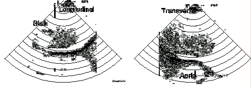
gifin c:\data\grid\mx4grd2t.gif
8.5132,5.0326,0 2.965517241
5. Rotate the transverse section 90 degrees:
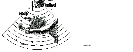
window 7.52,4 13,8,2
rotate3d y 10,8,0 90
6. Move the rotated transverse section over to the longitudinal section:
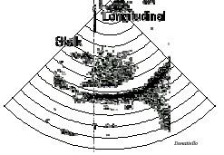
move window 9,4 11,8.2
10,8,0 5,8,0
7. Now, the Dview command can be used as above
Back to E-chocardiography Home Page.
e-mail:shindler@umdnj.edu